Cameras, lights, and points of interest
1. Create a camera layer and change camera settings
You can view 3D layers from any angle and distance using camera layers. Just as it's easier in the real world to move cameras through and around a scene than it is to move and rotate the scene itself, it's often easiest to get different views of a composition by setting up a camera layer and moving it around in a composition.
You can configure the camera by modifying and animating the camera settings, You can also use camera settings to add camera-like behavior to compositing effects and animations.
The camera affects all 3D and 2D layers. You can use perspective cameras (movies) or lighting to view or illuminate the effects from various angles to simulate more complex 3D effects.
You can choose to view the project with an active camera or with a custom camera that you specify. The active camera is the topmost camera in the Timeline panel for which the Video switch is selected at the current time. The active camera view is the viewpoint used to create the final output and nested items. If you did not create a custom camera, the active camera is the same as the default project view.
All cameras are listed in the 3D Scene layer at the bottom of the Project panel, and you can access them at any time.
It is usually easiest to adjust the camera when using a custom 3D scene. Of course, when you look through the camera itself, you cannot view the camera operation.
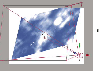
Example of a camera
A. Point of interest B. Frame C. Camera
Note : The effects of 3D scene layers affect the entire project.
1.1 Create a camera layer
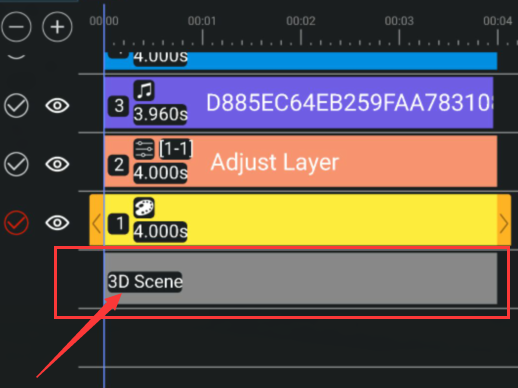
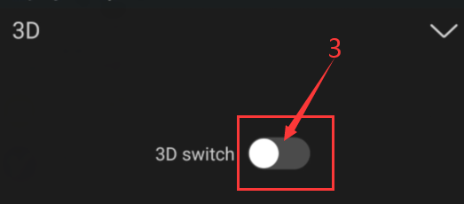
To create camera layer, select Layer> 3D> Turn on 3D Switch.
This is the 3D scene layer that appears at the bottom of the project's layers at this time.
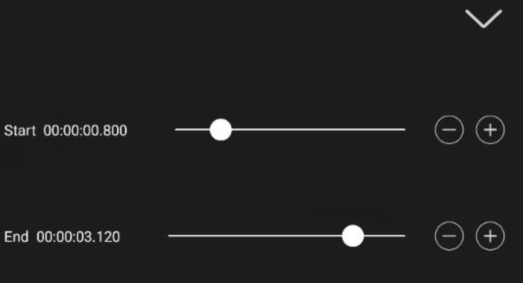
Note : By default, the 3D scene layer starts at the beginning of the project duration. To the end of the duration of the project. And you can set the time range of the camera to control how long the camera will affect the project.
1.2 Create and delete camera type
The perspective camera is a composition picture that displays the image of the three-dimensional and three-dimensional space on the two-dimensional plane according to the visual habits of the human eye. The ortho camera does not consider the perspective effect of the object, but only one-to-one corresponds the points in the three-dimensional space where the object is located to the imaging on the two-dimensional view plane. That is, a perspective camera has a strong expression of three-dimensional space, and an ortho camera can accurately express the position and state of an object in space.
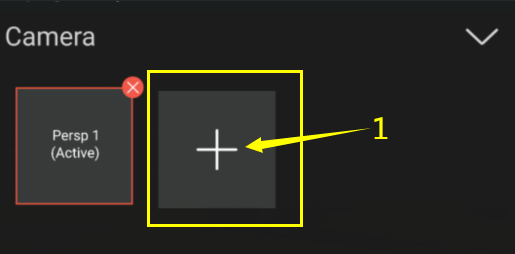
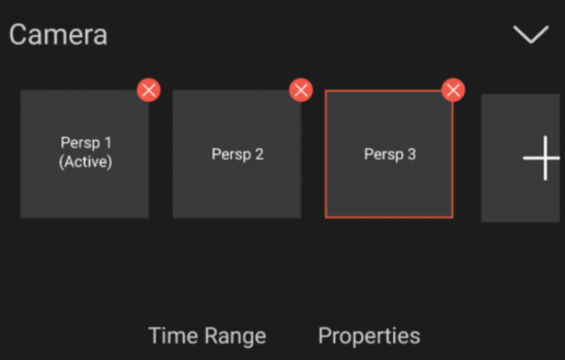
By default, Persp 1 (Active) is the name of the first camera you created in your project, and all subsequent cameras are numbered in ascending order. Choose different names for multiple cameras to distinguish them.
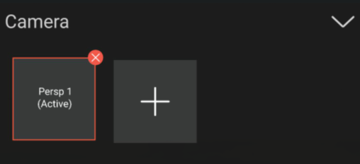
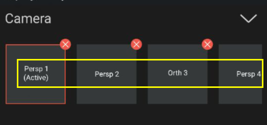
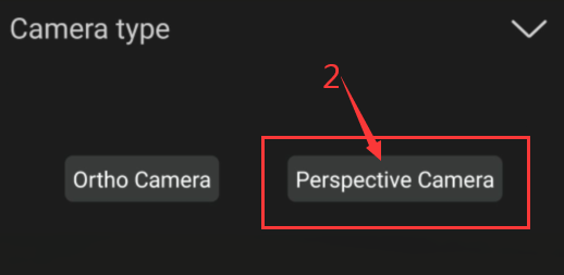
●To add cameras of the same type, click the '+' sign to the right of the camera name and click the Perspective Camera.
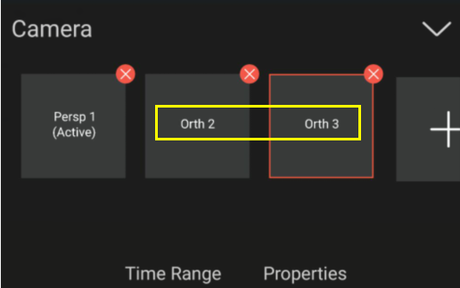
●To add a different type of camera, click the '+' sign to the right of the camera name and click the ortho camera.

●To delete an added camera, click the "x" in the upper right corner of the camera to delete it.
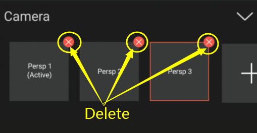
Note : There must be at least one camera in the 3D scene layer.
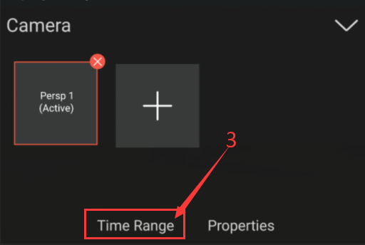
1.3 Change camera settings
You can change camera settings at any time.
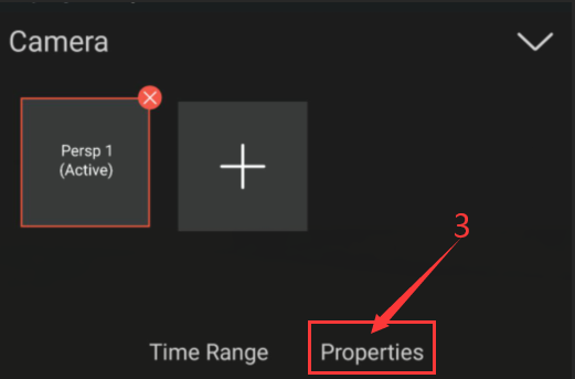
●To change the attribute value of a camera layer, Select 3D Scene Layer> Camera >Properties.
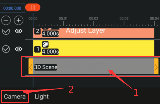
● To change the duration range affected by the camera layer, select 3D Scene Layer> Camera> Time Range.
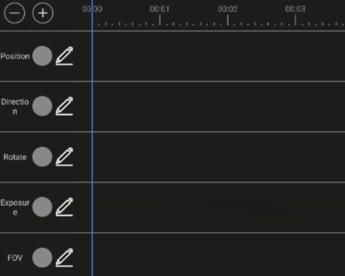
1.4 Camera settings
FOV FOV refers to the range covered by the camera lens. Objects beyond this angle will not be taken into the lens.
Note : Ortho cameras have no FOV attributes.
2. Create a light and change light settings
A light layer can affect the colors of the 3D layers that it shines on, depending on the light’s settings and the Material Options properties of the 3D layers. Each light, by default, points to its point of interest.
Lighting can be used to illuminate and project 3D layers. You can use lighting to match the lighting conditions of the scene in which you have projects or create more interesting visual effects. For example, you can use a lighting layer to create the look of light that hits a video layer as if it were made of stained glass.
Lighting affects all 3D layers in the project.
In addition to lighting types, you can animate all other settings for lighting.
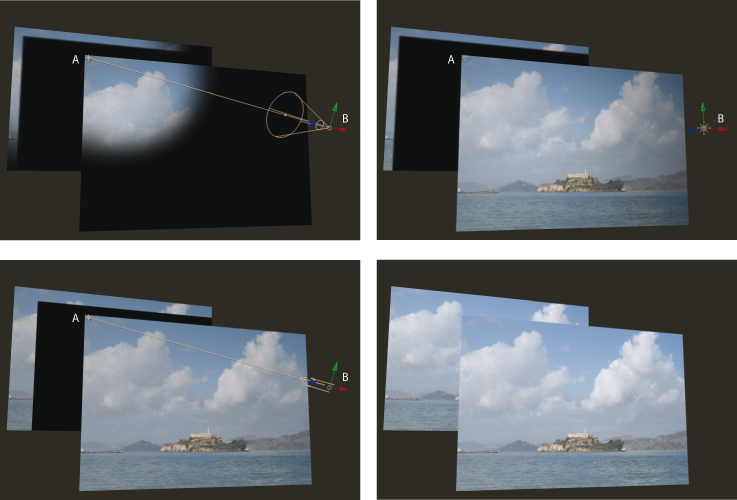
Light types: Spot (upper-left); Point (upper-right); Parallel (lower-left); Ambient (lower-right)
A. Point of interest B. Light icon
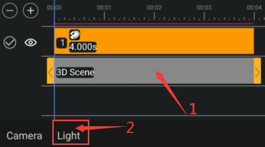
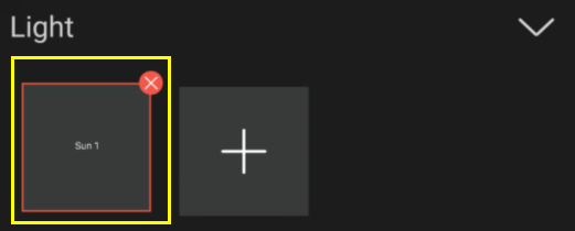
2.1 Create a light
● To create a light, select Layer> 3D> Turn on 3D Switch.
The light you create includes name of the type of light. For example, if you add a spot light, it is named 'Spot Light 1'.By default, the generated light type name is 'Sun 1'.
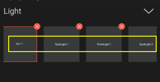
And all subsequent lights of the same type are numbered in ascending order. Choose different names for multiple cameras to distinguish them.
Note : By default, the 3D scene layer starts at the beginning of the project duration. By the end of the project period. You can set the time range of the lighting to control how much the lighting affects the project.
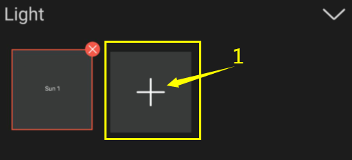
● To add other types of lighting, click the "+" sign to the right of the lighting name, and then click Spotlight or Point Light.

2.2 Change light settings
● To change the value of the light's properties, choose 3D Scene Layer> Light> Select Light> Light Properties.
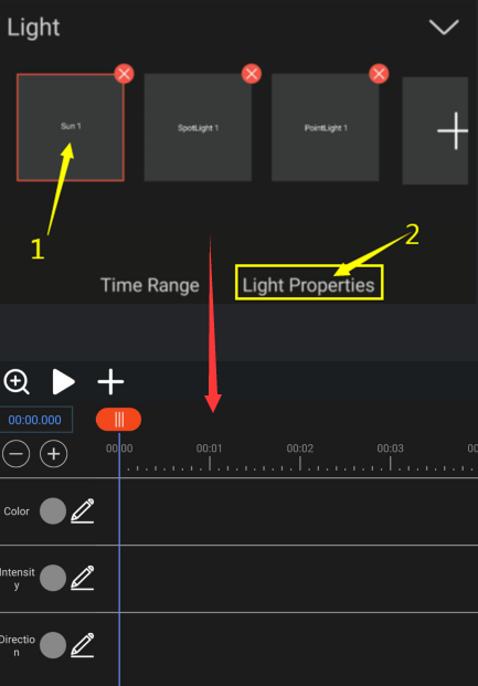
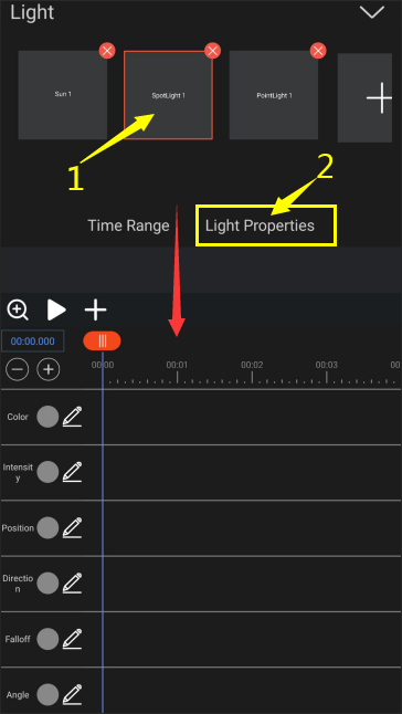
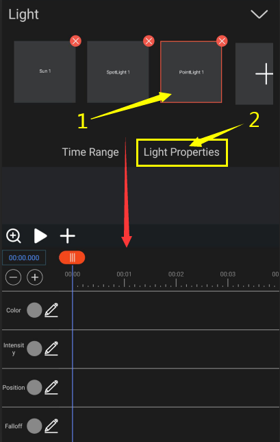
● To change the duration of the project affected by light, select 3D Scene Layer> Camera> Time Range.
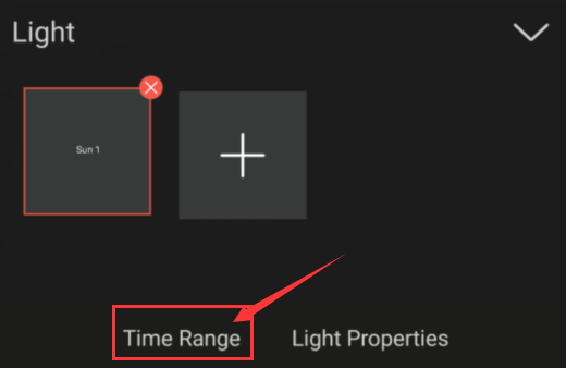

2.3 Light settings
Light Type Parallel emits directional, unconstrained light from an infinitely distant source, approximating the light from a source like the Sun. Spot emits light from a source constrained by a cone, like a flashlight or a spotlight used in stage productions. Point emits unconstrained omnidirectional light, like the rays from a bare light bulb.
Intensity The brightness of the light. Negative values create nonlight. Nonlight subtracts color from a layer. For example, if a layer is already lit, creating a directional light with negative values also pointing at that layer darkens an area on the layer.
Color The color of the light.
Cone Angle The angle of the cone surrounding the source of a light, which determines the width of the beam at a distance. This control is active only if Spot is selected for Light Type.
Falloff The type of falloff for a parallel, spot, or point light. Falloff describes how a light’s intensity is lessened over distance.The attenuation here specifies the distance at which the light is attenuated.
3. move a camera, light, or point of interest
Camera layers and light layers each include a Point Of Interest property, which specifies the point in the composition at which the camera or light points. By default, the point of interest is at the center of the composition. You can move the point of interest at any time.
● Select the attributes of the camera or lighting, and modify the position and orientation attribute values.
4. Move or adjust camera or 3D scene to view layers
You can change the perspective and orientation of the view to see the selected layer.
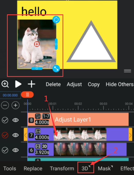
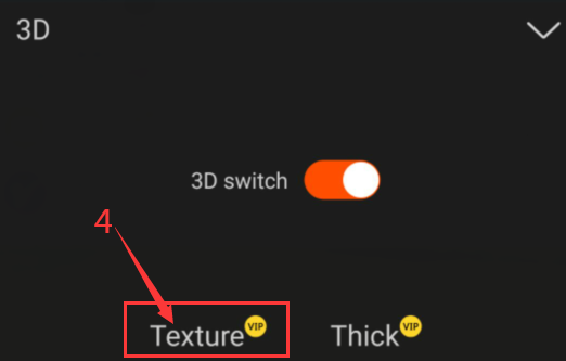
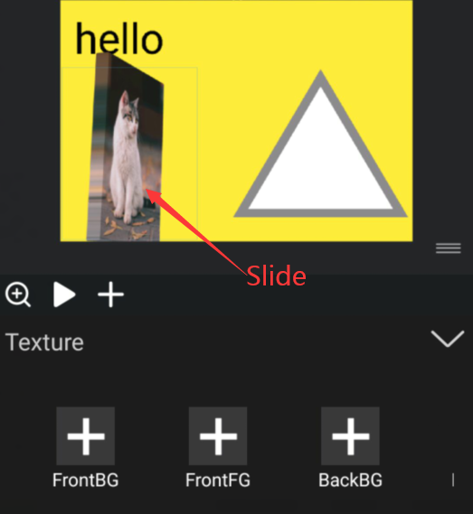
Select the layer, click 3D> turn on the 3D switch> click Texture, and then slide panel B with your finger to cut the perspective.
5. Material Options properties
3D layers have Material Options properties, which determine how a 3D layer interacts with light and shadow.
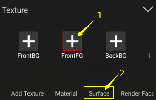
● To modify material properties, select Layer> Click 3D> Turn on 3D Switch> Click Texture> Select a Face> Click Surface.
Metallic The metallic property defines whether the surface is a metallic (conductor) or a non-metallic (dielectric) surface.
This property can dramatically change the appearance of a surface. Non-metallic surfaces have chromatic diffuse reflection and achromatic specular reflection (reflected light does not change color). Metallic surfaces do not have any diffuse reflection and chromatic specular reflection (reflected light takes on the color of the surfaced as defined by baseColor).
The effect of metallic is shown in figure .

metallic varying from 0 (left) to 100 (right).
Reflect The reflectance property only affects non-metallic surfaces. This property can be used to control the specular intensity and index of refraction of materials. This value is defined between 0 and 100 and represents a remapping of a percentage of reflectance. For instance, the default value of 50 corresponds to a reflectance of 4%. Values below 35 (2% reflectance) should be avoided as no real-world materials have such low reflectance.
The effect of reflectance on non-metallic surfaces is shown in figure.

reflectance varying from 0 (left) to 100 (right).
Rough The roughness property controls the perceived smoothness of the surface. When roughness is set to 0, the surface is perfectly smooth and highly glossy. The rougher a surface is, the “blurrier” the reflections are. This property is often called glossiness in other engines and tools, and is simply the opposite of the roughness (roughness = 100 - glossiness).
Clear coat Multi-layer materials are fairly common, particularly materials with a thin translucent layer over a base layer. Real world examples of such materials include car paints, soda cans, lacquered wood and acrylic.
The clearCoat property can be used to describe materials with two layers. The clear coat layer will always be isotropic and dielectric.
![]()
Comparison of a carbon-fiber material under the standard material model (left) and the clear coat model (right).
The clearCoat property controls the strength of the clear coat layer. This should be treated as a binary value, set to either 0 or 100. Intermediate values are useful to control transitions between parts of the surface that have a clear coat layers and parts that don't.
The effect of clearCoat on a rough metal is shown in figure.
![]()
clearCoat varying from 0 (left) to 100 (right).
Note : The clear coat layer effectively doubles the cost of specular computations. Do not assign a value, even 0, to the clear coat property if you don't need this second layer.
Clear Rough The clearCoatRoughness property is similar to the roughness property but applies only to the clear coat layer.
The effect of clearCoatRoughness on a rough metal is shown in figure.
![]()